


Unipi Extension xS53
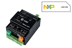
Unipi Extension xS53 is an extension module communicating via the RS-485 serial interface (Modbus RTU). The module is a simple and inexpensive method of extending your project by additional inputs & outputs. The xS53 features a set of analog inputs, but also digital inputs and outputs. This makes it suitable for implementation in more complex projects involving the measurement of analog components. The module is designed for installation on a DIN rail and is compatible with Unipi controllers, as well as PLCs from other vendors.
240,50 € excl. VAT
In stock > 20 pcs
Extra > 50 pcs within 10 days after ordering
Check availability
Product description
Unipi Extension xS53 is an extension module communicating via the RS-485 serial interface (Modbus RTU). The module is a simple and inexpensive method of extending your project by additional inputs & outputs. The xS53 features a set of analog inputs, but also digital inputs and outputs. This makes it suitable for implementation in more complex projects involving the measurement of analog components. The module is designed for installation on a DIN rail and is compatible with Unipi controllers, as well as PLCs from other vendors.
Basic features
| Digital inputs | 4 | Common features RS-485 serial interface (Modbus RTU) Aluminum chassis (IP20) Power supply: 24 V⎓, 0.5 A |
| Relay outputs | 5 | |
| Analog inputs (voltage, current) | 8 | |
| RS-485 serial interface | 1 |
Inputs & outputs description
Digital inputs (DI) are designed to read binary logic states represented by direct voltage levels. That makes them suitable for reading data from various binary sensors and devices such as switches (on/off), motion sensors (movement detected/not detected), liquid level sensors (full tank/empty tank), etc. All digital inputs also feature counter functionality by default.
Relay outputs (RO) are primarily used for switching two-state devices with higher current draw such as lightbulbs, thermoelectric valve drives, water heaters, pumps, etc.
Analog inputs (AI) are designed to measure 0-10 V⎓ voltage and 0-20 mA current, which makes them suitable for collecting data from analog sensors.
Communication interfaces
Extension modules communicate through the RS-485 interface (Modbus protocol). Instructions for connection and commissioning, including a description of SW and HW configuration of communication parameters, can be found on this link.
Other functions
Along with standard inputs and outputs, the module also features other functions broadening its possible uses. For more information on these features, please visit our Knowledge Base.
- Direct Switch
- Default settings
- Master Watchdog
- Manual and software configuration of communication parameters
- User-freely programmable LEDs
Package contents
- extension module
- removable screw terminals
- DIN rail holder (35 mm)
- 3× DIN rail holder mounting screws
- 1× grounding screw
Extension modules overview |
||||||
| Name | DI | DO | RO | AI | AO | RS-485 |
| Extension modules, the size on DIN rail: 4 modules = 7 cm | ||||||
| xS11 | 12 | - | 13 | - | - | 1 |
| xS51 | 4 | - | 5 | 4 (voltage, current, resistance) | 4 | 1 |
| xS52 | 4 | - | 5 | 8 (resistance) | - | 1 |
| xS53 | 4 | - | 5 | 8 (voltage, current) | - | 1 |
| xS54 | 4 | - | 5 | 8 (voltage, current, resistance) | - | 1 |
Further information
Documentation
|
Product leaflet Product line information |
download | |
|
Modbus register map Table overview of Modbus registers |
download | |
|
Certification Declaration of conformity |
download | |
|
Product datasheet Product features and technical information |
download | |
|
Instruction leaflet Quick instructions and safety information |
download |
Detailed parameter information and exact I/O specifications can be found in the datasheet.
| Digital inputs | 4 |
| Relay outputs | 5 |
| Analog inputs | 8 |
| RS485 interface | Yes |
| Power | 24V DC, 0.5 A |
| Dimensions | 72 × 90 × 56 mm |
| Mounting | DIN rail (35 mm) |
| Weight | 320 g |
Related products
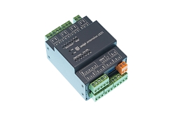
321,00 €
265,29 € excl. VAT
Extra > 50 pcs within 10 days after ordering
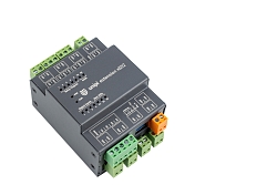
291,01 €
240,50 € excl. VAT
Extra > 50 pcs within 10 days after ordering
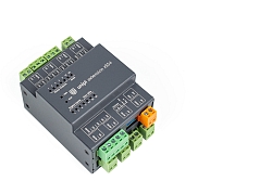
321,00 €
265,29 € excl. VAT
Extra > 50 pcs within 10 days after ordering
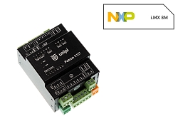
479,00 €
395,87 € excl. VAT
Extra > 20 pcs within 10 days after ordering
583,00 €
481,82 € excl. VAT
Extra > 10 pcs within 10 days after ordering