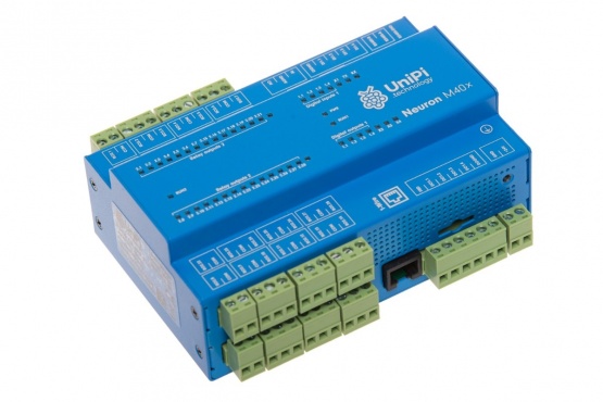
Unipi Neuron M403
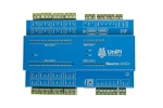
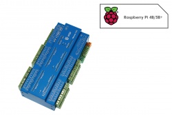
Unipi Neuron M403 is a programmable logic controller (PLC) designed for automation, control, regulation and monitoring. The L303’s specialised architecture was designed with a high number of relay outputs in mind. With 28 RO’s, it is suitable for monitoring of external devices or reading data from various digital sensors or energy meters. The controller is also provided with a 1-Wire interface for connection of digital temperature or humidity sensors.
Note: The product was discontinued
Features
- high number of relay outputs
- compact size, durable aluminium chassis (IP20 protection)
- integrated Raspberry Pi Model 3B computer (quad-core CPU, 1 GB RAM)
- designed for DIN rail mounting
- features RS485 serial line for Modbus communication
- software openness (based on Linux OS)
- Mervis lifetime license as part of the package
Discontinued
Basic description
Unipi Neuron M403 is a programmable logic controller (PLC) designed for automation, control, regulation and monitoring. The L303’s specialised architecture was designed with a high number of relay outputs in mind. With 28 RO’s, it is suitable for monitoring of external devices or reading data from various digital sensors or energy meters. The controller is also provided with a 1-Wire interface for connection of digital temperature or humidity sensors.
Basic features
| Digital inputs | 4 | Common features Raspberry Pi 3 Model B computer (1,2GHz quad-core CPU, 1GB RAM) 4× USB 2.0 1× 10/100Mbit Ethernet Wi-Fi, Bluetooth, HDMI port Aluminium chassis (IP20) |
| Digital outputs | 4 | |
| Relay outputs | 28 | |
| Analog inputs | 1 | |
| Analog outputs | 1 | |
| RS485 serial interface | 1 | |
| 1-Wire bus | 1 |
Inputs & outputs description
Digital inputs (DI) are designed to read binary logic states represented by direct voltage levels. That makes them suitable for reading data from various binary sensors and devices such as switches (on/off), motion sensors (movement detected/not detected), liquid level sensors (full tank/empty tank) etc.
Digital outputs (DI) are intended for switching various binary devices (lighting, smart door locks, drives of shutters and blinds etc.) through direct voltage. DO's also feature a Pulse-Width Modulation (PWM) function allowing to use the output for analog control.
Analog input (AI) is designed to measure voltage, current or resistance to read values from various analog sensors such as thermometers, pressure meters, tensometers etc.
Analog output (AO) serves for control of multi-state external devices through direct voltage or current and is suitable for control and regulation of devices such as three-way valves, heat exchangers, electric motors etc.
Computing module
As a computing module, the Neuron controllers use the Raspberry Pi 3 Model B featuring quad-core 1.2GHz CPU and 1GB RAM. That gives them more than enough performance for various performance-demanding applications. MicroSD memory cards are used as system storage, which must be purchased separately.
Communication interfaces
Neuron controllers are by default provided with RS485 serial lines. This type of interface usually uses the Modbus RTU protocol and can be used to communicate with various devices such as Extension xS extension modules, energy meters, touchscreen HMI displays, controllers from other vendors, various sensors etc. A single bus can support dozens of devices while the bus' length can reach up to several hundred meters.
A single 1-Wire bus is also included. This interface uses 2-3 conductors for collecting data from various 1-Wire sensors such as thermometers, humidity meters, light intensity sensors etc.). A single 1-Wire bus supports up to 15 devices, the overall length of the bus can reach up to 100 meters.
All Neuron models also feature a single 10/100Mbit Ethernet port for network communication
Software options
Thanks to the software openness of Unipi controllers customers can choose from a broad range of software solutions and are not limited to a single platform Among supported solutions are both commercial and open-source systems. Visit the Other software overview for the list of other supported solutions.
The main supported solution is the Mervis control system - a platform developed under the IEC 61131-3 standard for PLC programming, that includes SCADA interface for remote management and monitoring, a comprehensible development environment, a human-machine interface (HMI) editor and an online/on-premise database for storing historical data and retrospective analysis of the controlled technology's operation.
Aside from commercial platforms you can also choose any from the list of supported open-source solutions, or use the EVOK API (Websocket, REST,...) Modbus TCP, SysFS or other tools for implementing your logic in any programming language. Visit this link for the list of supported software solutions.
Package contents
- Neuron controller
- removable screw terminals
- DIN rail holder (35 mm)
- 3× DIN rail holder mounting screws
- 1× grounding screw
- instruction leaflet
- lifetime Mervis license code
Other features
All components of the controller are encased within a durable aluminium chassis (IP20 protection). The controller is designed for mounting on a standard DIN rail (35 mm).
Neuron product line overview
| Model | DI | DO | RO | AI | AO | RS485 | Common features |
| Type S, size on a DIN rail = 4 modules = 7 cm | |||||||
| S103 (Raspberry Pi 4) | 4 | 4 | - | 1 | 1 | 1 | Raspberry Pi 4 Model B (quad-core 1.5 GHz CPU) selectable RAM capacity (2/4/8 GB) 2× USB 2.0, 2× USB 3.0 1× 1Gbit Ethernet Wi-Fi, Bluetooth (2× micro HDMI port) Aluminium chassis (IP20, heatsink) |
| S103 | 4 | 4 | - | 1 | 1 | 1 | Raspberry Pi 3 Model B (quad-core 1.2 GHz CPU) 1 GB RAM 4× USB 2.0 1× 10/100Mbit Ethernet Wi-Fi, Bluetooth (HDMI port) Aluminium chassis (IP20) |
| Type M, size on a DIN rail = 8 modules = 14 cm | |||||||
| M103 | 12 | 4 | 8 | 1 | 1 | 1 | |
| M203 | 20 | 4 | 14 | 1 | 1 | 1 | |
| M303 | 34 | 4 | - | 1 | 1 | 1 | |
| M523 | 8 | 4 | 5 | 5 | 5 | 2 | |
| Type L, size on a DIN rail = 12 modules = 21 cm | |||||||
| L203 | 36 | 4 | 28 | 1 | 1 | 1 | |
| L403 | 4 | 4 | 56 | 1 | 1 | 1 | |
| L523 | 24 | 4 | 19 | 5 | 5 | 2 | |
| L533 | 12 | 4 | 10 | 9 | 9 | 3 | |
Further info
Documentation
|
Modbus register map Table overview of Modbus registers |
download | |
|
Certification Declaration of conformity |
download | |
|
Manual User guide and technical documentation |
download | |
|
Product datasheet Product features and technical information |
download | |
|
Instruction leaflet Technical and safety information |
download | |
|
Product leaflet Product line information |
download |
| Digital inputs | 4 |
| Relay outputs | 28 |
| Transistor outputs | 4 |
| Analog inputs | 1 |
| Analog outputs | 1 |
| RAM | 1 GB |
| CPU | 4 × 1 GHz |
| RS485 interface | Yes |
| Ethernet | 10/100 BaseT |
| USB 2.0 | 4 |
| 1-Wire bus | Yes (galvanically isolated) |
| Power | 24 V DC |
| Dimensions | 140 mm × 90 mm × 60 mm |
| Mounting | DIN (35 mm) |
| Weigth | 350 g |
| RTC backup | maximum 7 days |
